
Steel Fiber Reinforced Concrete (SFRC): Types, Properties, Dosage & Applications
September 23, 2026
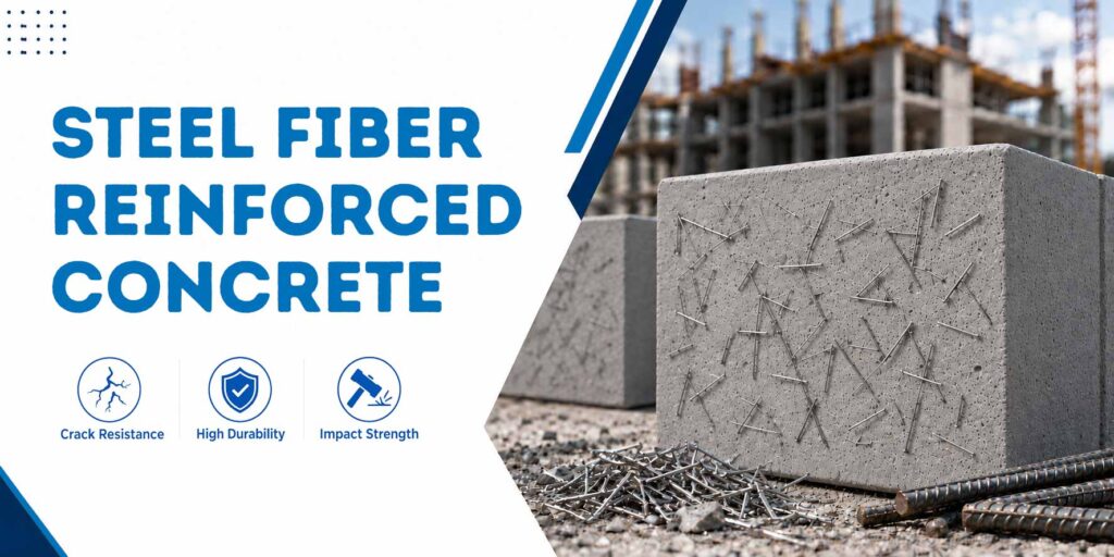
Steel Fiber Reinforced Concrete (SFRC) is concrete in which short steel fibers are distributed throughout the concrete matrix to improve its post-cracking performance. Depending on the fiber geometry, length, diameter, aspect ratio, and dosage, steel fibers can improve crack control, residual strength, impact resistance, fatigue performance, and flexural toughness.
What Is Steel Fiber Reinforced Concrete?
Plain concrete is strong in compression but comparatively weak in tension. Once tensile cracks form, its ability to carry load reduces significantly.
Steel fiber-reinforced concrete addresses this limitation by introducing short steel fibers into the concrete matrix. The fibers bridge cracks as they form and help the concrete retain load-carrying capacity after cracking.
Unlike traditional reinforcement, which is placed at predetermined locations, steel fibers are distributed throughout the concrete matrix. Their performance depends on factors such as fiber length, diameter, aspect ratio, geometry, and dosage.
How Do Steel Fibers Work in Concrete?
As cracks develop because of shrinkage, loading, or impact, steel fibers cross the crack and transfer stress across the opening. This improves the post-cracking behaviour of the concrete and increases its toughness and energy absorption capacity.
The way a fiber anchors into concrete depends on its shape. Hooked and crimped fibers use mechanical anchorage, while straight fibers mainly rely on friction between the fiber and the surrounding concrete.
Fiber length controls the anchoring length and the chance of a fiber bridging a crack. Fiber diameter and aspect ratio also affect post-crack strength and energy absorption.
Types of Steel Fibers Used in Concrete
Steel fibers are available in different shapes and sizes. The geometry affects how well a fiber anchors into concrete and resists being pulled out.
Common types include hooked-end, micro, crimped/wavy, and straight fibers.
Hooked-End Fibers
Hooked-end fibers have bent ends that provide strong mechanical anchorage inside the concrete. They are used in applications including industrial floors, warehouse slabs-on-grade, precast tunnel segments, and pavement overlays.
Typical lengths include 30 mm, 35 mm, 50 mm and 60 mm, with aspect ratios of 50–65. The hooked ends act as small anchors and require more energy to pull out of the concrete.
Micro Steel Fibers (Brass/Copper-Coated)
Micro steel fibers are short, fine fibers used in applications such as Ultra-High-Performance Concrete (UHPC), military blast slabs, bank vaults, and specialised structural repair grouts.
Typical lengths include 6 mm and 13 mm, with aspect ratios of 60–80. Brass/copper-coated micro fibers have a high surface area and high tensile wire strength.
Crimped/Wavy Fibers
Crimped or wavy fibers have a continuous wave shape that provides mechanical anchorage along the fiber length. They are used in applications including wet- and dry-mix shotcrete, infrastructure tunnels, slope stabilisation and high-impact industrial hardstandings.
Typical lengths include 25 mm, 30 mm and 50 mm, with aspect ratios of approximately 45–60.
Straight Fibers
Straight steel fibers have no mechanical deformation and rely mainly on friction with the surrounding concrete. They are used for secondary shrinkage control, thin-sheet architectural paneling and specialised mixes.
Typical lengths include 12 mm, 20 mm and 30 mm, with aspect ratios of approximately 60–80.
Steel Fiber Classifications and Specifications
| Fiber type | Typical length | Typical aspect ratio (L/d) | Main applications |
|---|---|---|---|
| Hooked-end | 30, 35, 50, 60 mm | 50–65 | Industrial floors, warehouse slabs, tunnel segments, pavements |
| Micro (brass/copper-coated) | 6, 13 mm | 60–80 | UHPC, specialised repair grouts, high-impact applications |
| Crimped/wavy | 25, 30, 50 mm | 45–60 | Shotcrete, tunnels, slope stabilisation, industrial hardstandings |
| Straight | 12, 20, 30 mm | 60–80 | Shrinkage control, thin-sheet applications, specialised mixes |
Standard macro-fiber lengths generally range from 25–60 mm, while micro-fibers generally range from 6–13 mm. Fiber diameter typically ranges from 0.4–1.0 mm. Aspect ratio varies by fibre geometry and typically falls within the ranges shown in the table.
Properties of Steel Fiber Reinforced Concrete
SFRC changes the behaviour of concrete after cracking. The fibers help hold cracked sections together and allow the concrete to continue carrying load after cracks develop.
Main Structural Benefits
- Post-Crack Strength: Steel fibers improve the ability of concrete to carry load after cracking.
- Impact Resistance: Fibers improve energy absorption when concrete is subjected to sudden or repeated impacts.
- Fatigue Resistance: SFRC can provide improved performance under repeated loading, making it useful in floors, pavements and other heavily trafficked applications.
- Crack Control: Fibers distributed throughout the concrete matrix help control crack development and crack opening.
- Flexural Toughness: Fiber bridging improves energy absorption and residual performance after cracking.
What Fibers Do Not Do?
Steel fibers should not be considered a direct replacement for all conventional reinforcement. Their structural contribution depends on the fiber type, dosage, concrete mix and project-specific design.
Steel fibers are designed to improve the behaviour of concrete after cracking. They should not be treated as a universal replacement for primary reinforcement.
| Property | Plain concrete | Steel fiber reinforced concrete |
|---|---|---|
| Post-crack behaviour | Rapid loss of load capacity | Improved residual load-carrying capacity |
| Impact resistance | Lower | Higher |
| Fatigue performance | Lower | Improved |
| Crack control | Limited | Improved |
| Flexural toughness | Lower | Higher |
| Compressive strength | Primarily governed by the concrete mix | Primarily governed by the concrete mix |
Steel Fiber Dosage and Mix Design
Steel fiber dosage is generally specified in kilograms per cubic metre (kg/m³) or as a percentage by volume. The required dosage depends on the application, loading conditions, concrete grade, fiber characteristics and required post-crack performance.
Dosage can be broadly grouped into low, medium and high ranges based on the required performance and application. Low dosages are mainly used to control plastic and drying shrinkage cracking. Medium dosages can improve fatigue resistance, impact strength and shear performance. Higher dosages are used for applications exposed to high dynamic, seismic or other extreme forces.
Indicative Steel Fiber Dosage Rates
| Application | Indicative dosage |
|---|---|
| Floor slabs / slabs-on-grade / industrial floors | 20–40 kg/m3 |
| Road pavements / sprayed shotcrete/tunnel linings | 30–60 kg/m3 |
| Precast structural elements / high-load structural nodes | 40–80 kg/m3 |
| Steel micro-fibers for early crack control / UHPC | 10–20 kg/m3 |
These ranges are indicative. The final dosage should be selected based on the project requirements and approved design.
Steel fiber dosage can also be expressed by volume. Based on a steel density of approximately 7,850 kg/m³, 0.5% steel fiber by volume is equivalent to approximately 39.25 kg/m³.
Disclaimer: Final fiber dosage must be determined based on project-specific structural requirements and the approved mix design.
Understanding Aspect Ratio and Fiber Balling
Aspect ratio is the ratio of fiber length (L) to its nominal diameter (d). It affects the fiber’s ability to bridge cracks, anchor into concrete, and contribute to post-crack strength.
Higher aspect ratios can improve post-cracking residual strength and energy absorption. However, when the aspect ratio becomes too high, fibers can become more flexible and interlock with each other during batching. Aspect ratios above 80 can increase the risk of fiber balling.
How to Prevent Fiber Balling?
- Add fibers gradually into an actively mixing concrete batch
- Use glued fiber bundles where suitable
- Make sure the concrete contains enough mortar to surround the fibers
- Control aggregate grading, fiber dosage, and mixing procedures
- Avoid adding fibers too quickly, as this can cause fibers to form tangled lumps
Workability and Standards
Adding steel fibers can reduce fresh concrete workability because the fibers increase internal friction within the concrete matrix.
IS 10262:2019 provides the basic framework for calculating the quantities of water, cement, fine aggregate, and coarse aggregate for concrete mix proportioning. However, it does not contain a separate mix-design procedure specifically for steel fiber concrete.
Fine aggregate: The fine-aggregate proportion should be increased by around 5–10% over standard IS 10262 proportions to provide a suitable mortar layer around the fibers.
Aggregate size: The nominal maximum aggregate size should be limited to 20 mm, and for dense, high-dosage structural mixes it may be preferable to use 10–12.5 mm aggregate.
Chemical admixtures: PCE-based superplasticisers can be used to improve workability and slump retention without increasing water content.
Large aggregates such as 40 mm can interfere with fiber distribution and increase the risk of segregation in high-dosage mixes.
External references such as ACI 544.3R and the UK Concrete Society’s TR34 may also be used for fiber reinforced concrete proportioning and production where appropriate.
Important: Water should not be added simply to restore workability because this can change the water cement ratio and affect concrete strength and performance.
Steel Fiber Reinforced Concrete vs Rebar
Steel fibers and conventional reinforcement serve different purposes and should not automatically be treated as interchangeable.
Steel fibers can be used in applications where distributed reinforcement is appropriate. In certain slabs, pavements, and similar applications, they may replace wire mesh or secondary reinforcement when permitted by the structural design.
They cannot automatically replace primary reinforcement in beams, columns or other structural elements where reinforcement is specifically designed to resist calculated forces.
| Aspect | Rebar / Mesh | Steel Fibers |
|---|---|---|
| Where reinforcement acts | At designed locations based on structural calculations | Distributed throughout the concrete matrix |
| Placement | Requires positioning and fixing | Incorporated into the concrete mix |
| Crack control | Controls cracks at reinforcement locations | Provides distributed crack control |
| Typical use | Primary and secondary reinforcement where structurally designed | Floors, pavements, shotcrete and other designed SFRC applications |
| Limitation | Requires correct positioning and fixing | Cannot automatically substitute for calculated primary reinforcement |
Advantages and Limitations of SFRC
Advantages
Distributed Crack Control: Fibers are distributed throughout the concrete matrix rather than being concentrated along specific reinforcement lines.
- Reduced Reinforcement Placement: In applications designed for fiber reinforcement, the need for cutting, placing, and tying conventional mesh can be reduced.
- Improved Toughness: Fibers improve post-cracking energy absorption and resistance to impact and repeated loading.
- Potentially Larger Pour Areas: In suitably designed floor applications, SFRC can allow larger panels and help optimise joint layouts.
Limitations
- Higher Material Cost: SFRC generally costs more than plain concrete because of the additional fiber material.
- Reduced Workability: Higher fiber dosages can make concrete more difficult to place and finish.
- Fiber Exposure: Poor finishing or incorrect fiber selection can result in exposed fiber ends at the surface.
- Mixing Requirements: Proper batching and mixing are important to prevent fiber balling and ensure uniform distribution.
Applications of Steel Fiber Reinforced Concrete
SFRC is used in applications where improved crack control, toughness, impact resistance and post-crack performance are required.
- Industrial and Warehouse Floors: SFRC is widely used in industrial floors and slabs-on-grade subjected to forklift traffic, storage loads and repeated wheel loading.
- Tunnel Linings and Shotcrete: Steel fibers can be incorporated into wet- and dry-mix shotcrete for tunnel linings, infrastructure tunnels and slope stabilisation, where improved toughness and crack control are required.
- Roads and Pavements: Fiber-reinforced concrete can be used in pavement applications subjected to repeated wheel loads and fatigue.
- Precast Elements: SFRC can be used in precast structural and infrastructure elements, including tunnel segments and other components where crack control and handling resistance are important.
- Airport Runways: SFRC can be considered for selected heavy-duty pavement applications, including airport pavement, subject to project-specific design.
- Machine Foundations and Heavy-Duty Hardstandings: SFRC can be considered for areas exposed to repeated impact, vibration and heavy industrial loading.
IRC: SP:46-2013 provides calculations for the structural contribution of fibres in suitable fibre-reinforced pavement designs. It also states that, for specific light-to-medium axle-load conditions, the design may allow a reduction in slab thickness of 15–20% and changes to conventional joint reinforcement requirements. These changes must be based on the applicable pavement design and project conditions.
Codes and Standards for Steel Fiber Reinforced Concrete
SFRC design and material compliance in India involves multiple standards rather than relying on a single document.
ASTM A820/A820M
ASTM A820/A820M provides material requirements for steel fibers used in fiber-reinforced concrete.
ASTM A820/A820M identifies five manufacturing types:
- Type I: Cold-drawn wire
- Type II: Cut sheet
- Type III: Melt-extracted
- Type IV: Mill-cut
- Type V: Modified cold-drawn wire
ASTM A820/A820M specifies requirements for fibre tensile strength, dimensions, bending performance and dimensional tolerances. High-performance steel fibres can have tensile strengths exceeding 1,100 MPa, depending on the fibre type and manufacturer. The standard also includes a cold-bend test.
EN 14889-1
EN 14889-1 specifies requirements for steel fibers used in concrete and provides a conformity-assessment framework.
EN 14889-1 provides two relevant conformity-assessment pathways:
- System 1 – Structural Use: Used when fibers are designed to contribute to load-bearing capacity or structural stability. This requires independent testing of residual flexural tensile strength.
- System 3 – Non-Structural Use: Used when fibers are primarily intended for secondary crack or shrinkage control.
EN 14651
EN 14651 specifies the test method for determining the flexural tensile strength of fibre-reinforced concrete, including residual flexural tensile strength after cracking.
ASTM C1609
ASTM C1609 evaluates the flexural performance of fibre-reinforced concrete, including its load-carrying behaviour after cracking.
fib Model Code 2010
fib Model Code 2010 provides guidance for the design and performance assessment of fibre-reinforced concrete, including the use of residual tensile performance in structural design.
IS 10262:2019
IS 10262:2019 provides the basic framework for concrete mix proportioning. For SFRC, additional engineering adjustments are required to account for the effect of fibers on workability, aggregate balance and fresh-concrete behaviour.
IS 456:2000
IS 456:2000 provides the general requirements for plain and reinforced concrete design. SFRC projects may require additional standards and guidelines depending on the application, material performance, and structural design requirements.
IRC: SP:46-2013
IRC: SP:46-2013 guides the design of fibre-reinforced concrete pavements. Depending on the pavement design, loading conditions, and project requirements, fibre reinforcement can contribute to the structural performance of the slab and may influence slab thickness and conventional reinforcement requirements.
IRC:112-2020
IRC:112-2020 provides the structural framework for concrete road bridges and includes provisions relevant to integrating fiber reinforcement into applicable bridge structures.
How Ready-Mix SFRC Is Produced and Delivered?
Producing SFRC begins with an engineered base concrete mix, with the required fiber dosage incorporated as part of the approved mix design.
Planned Mix
The required fiber type, length, diameter, aspect ratio and dosage are determined according to the project’s performance requirements.
Controlled Fiber Addition
Steel fibers are introduced into the mixing process in a controlled manner to promote uniform dispersion and reduce the risk of fiber balling.
Quality Control
A wash-out test can be used to verify the actual fiber content in fresh concrete before it is discharged.
The wash-out test is an important QC measure because it is not possible to visually confirm the fibre dosage once the fibres are dispersed through fresh concrete.
Wash-Out Test
A representative fresh concrete sample of around 5–10 litres can be taken from the middle third of the transit mixer’s discharge.
The sample is weighed first. It is then washed through a suitable mesh while being agitated to remove the cement paste, admixtures and fine particles.
The remaining coarse aggregate and steel fibers are separated. Because steel is magnetic, magnetic separation or manual sorting can be used to isolate the fibers.
The recovered fibers are dried and weighed. The dry fibres should be weighed using a calibrated digital scale with a resolution of approximately ±0.1 g.
The recovered fiber mass is divided by the known sample volume to calculate the actual fiber dosage in kg/m³. This value is then compared with the plant batch ticket. Where required, individual fibers can also be counted to check distribution.
Aparna RMC SFRC
Aparna RMC supplies plant-batched steel fiber-reinforced concrete as Ducticrete, with fiber dosage selected according to the requirements of the application. Contact Aparna RMC for project-specific requirements and quotations.
Frequently Asked Questions On Steel Fiber Reinforced Concrete
Steel Fiber Reinforced Concrete (SFRC) is concrete containing discontinuously distributed steel fibers that bridge cracks and improve post-cracking behaviour, flexural toughness, impact resistance and crack control.
SFRC generally costs more than conventional concrete of the same grade because of the additional steel fiber material. The final cost depends on the fiber type, dosage, concrete grade, application and project requirements.
For a project-specific quotation, contact the Aparna RMC technical team.
No. Steel fibers cannot automatically replace primary reinforcement in beams, columns or other structural elements requiring designed reinforcement.
However, in specific slab, pavement and other applications, steel fibers may replace wire mesh or secondary reinforcement where permitted by the structural design.
The required dosage depends on the application and structural requirements. Indicative ranges include 20–40 kg/m³ for industrial floors, 30–60 kg/m³ for road pavements, sprayed shotcrete and tunnel linings, 40–80 kg/m³ for precast structural and high-load applications, and 10–20 kg/m³ for steel micro-fibers used for early crack control or UHPC.
SFRC is governed through a framework of relevant Indian standards rather than one standalone code. Relevant standards and guidelines include IS 456:2000, IS 10262:2019, IRC: SP:46-2013 and IRC:112-2020, depending on the application and design requirement.
SFRC is commonly used in industrial floors, slabs-on-grade, pavements, tunnel linings, shotcrete, precast elements, and other applications that require improved crack control, toughness, impact resistance, and post-cracking performance.
The concrete’s alkalinity generally protects steel fibres embedded in concrete under normal conditions. However, protection depends on crack width, concrete cover and exposure conditions. Marine or chloride-rich environments require additional consideration because corrosion can occur where fibres are exposed through cracks.
Categories
Recent Posts
- Steel Fiber Reinforced Concrete (SFRC): Types, Properties, Dosage & Applications
- M10 Concrete Ratio: Mix Proportion, Quantities and Uses
- How Ready Mix Concrete Is Made: The RMC Manufacturing Process, Step by Step
- What Is Ready Mix Concrete? A Complete Guide to RMC in Construction
- Fiber Reinforced Concrete (FRC): Types, Properties, Dosage and Applications
Connect with us